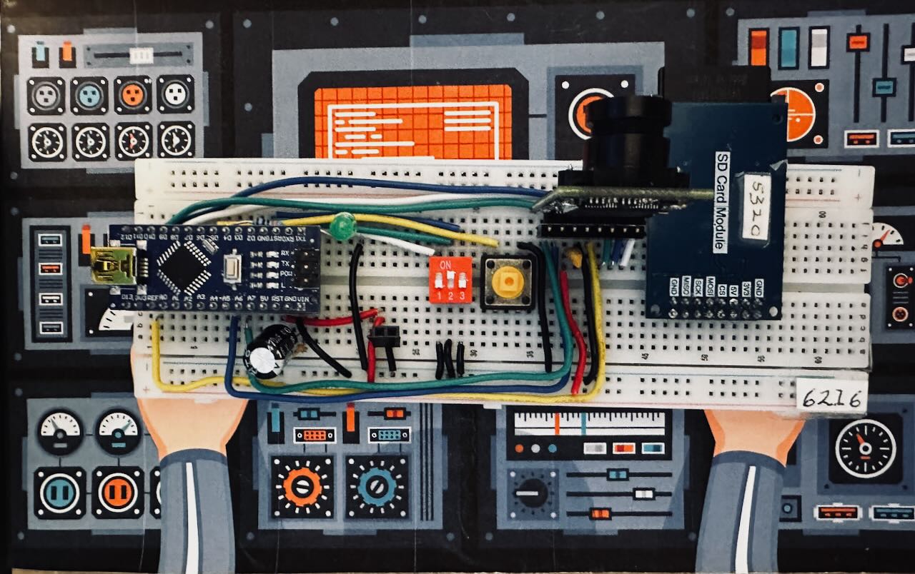
Rig 6216 is the working breadboard test platform for the SacL5 Balloon Device Project. Its purpose is to bring the camera, SD card module, DIP switch, button, LED indicator, power distribution, and Arduino Nano together in a visible, testable form before anything is soldered into the flight build.
The rig is deliberately laid out as a component verification breadboard, not as a compact final assembly. The goal is to make every connection traceable by eye, by schematic, and by pinout table. This lets the builder confirm each subsystem one step at a time: LED behavior, DIP switch mode selection, button input, camera SPI communication, SD card access, and shared power and ground routing.
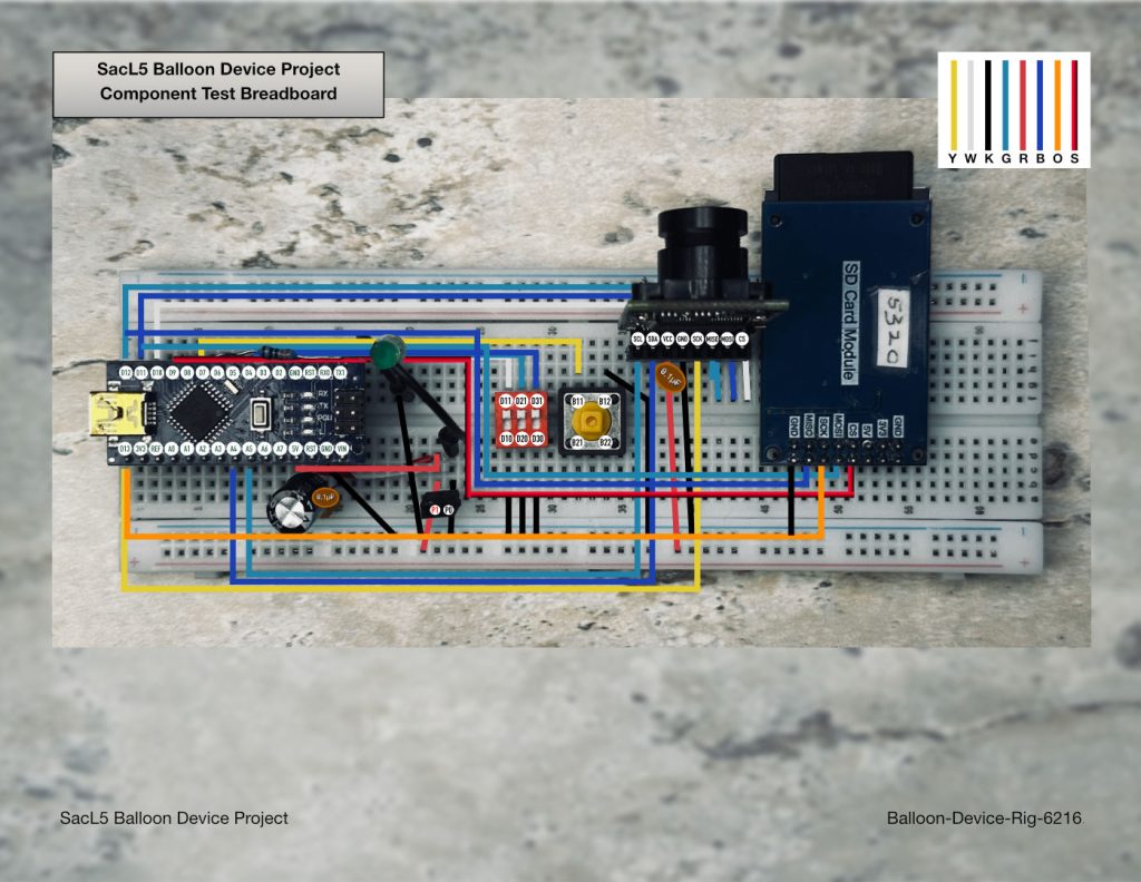
The physical rig photo shows the actual breadboard assembly used during bring-up. The Arduino Nano sits on the left, with the ArduCAM camera module and SD card module on the right. Between them are the supporting controls and indicators: the DIP switch for mode selection, the pushbutton for manual input testing, the external LED and resistor, and the shared power and ground wiring. This is the “truth on the bench” view: what was actually wired and tested.
The wire schematic overlays the same rig with color-coded signal paths. It acts as the bridge between the physical breadboard and the logical pinout tables. Rather than relying on memory or wire color alone, the schematic makes the SPI bus, I2C camera control lines, chip-select lines, power rails, and ground returns visually explicit. This is especially important because the camera and SD card share the SPI lines while using separate chip-select pins.
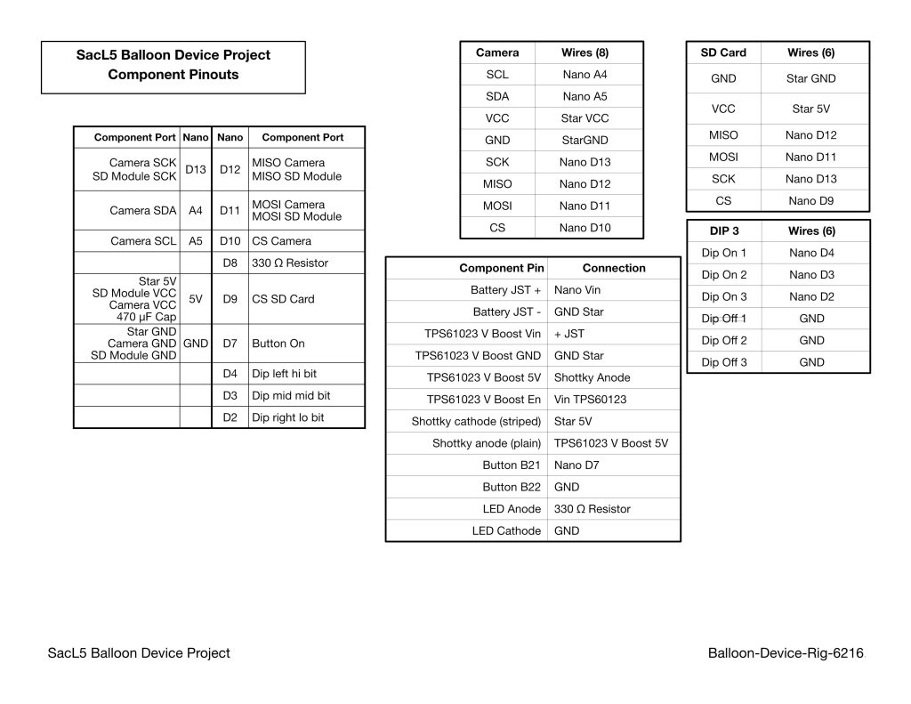
The pinout tables provide the formal wiring reference. They identify each Arduino Nano pin, the corresponding component connection, and the shared buses. The tables also document the star ground and star 5V distribution points, the button and LED wiring, the DIP switch bit assignments, and the boost/power routing. These tables are intended to be the authority used when checking the breadboard, rebuilding the rig, or transferring the design to a soldered board.
Together, the physical rig, wire schematic, and pinout tables form the build record for Rig 6216. They allow the project to move from “it works on the breadboard” toward a soldered, flight-ready assembly without losing the hard-won details discovered during component bring-up. In a project like this, the documentation is not decoration; it is part of the test equipment.